>>> Click here to access this episode of the Syllab Podcast on Spotify <<<
a) From source to sofa
It is a long journey from the source of a signal, the place where it is recorded, until its ultimate consumption on a TV screen, perhaps in your living room. A voyage with many intermediary steps and technologies, many of which we have either fully or partially covered at some stage during the previous seven chapters of this fourth series. Hence, let us describe these various processes from a very high level and then in the next sections we can zoom in on those aspects that deserve our full attention and curiosity but have not been dealt with previously.
Recording video entails capturing, storing and encoding both audio inputs and a stream of images. We have seen how sound could be transduced into an electrical signal thanks to a microphone in S4 Section 4.d on the telephone and in fact we also learned the same process applied in reverse underpins speakers’ technology. What we did not see then was how a recorded video signal is formatted, even though we looked at modern coding and decoding programs for the purpose of compression of data packets travelling along the internet in S4 Section 6.d, so we will look into this in the next section before progressing to the next phase, the signal transmission, in section c). We have already looked at radio broadcasting in depth in S4 Section 5.a therefore we will not repeat the fundamental concepts behind the modulation of an analog signal or the more contemporary use of analog sine waves as carriers on which to encode digital information (S4 Section 4.a). Instead, the focus will be on understanding those aspects that differ from radio broadcast, including the multiplexing because video clearly requires more bandwidth than audio.
As for the signal communication and reception, when considering radio waves we have also looked at the antenna, and we covered coaxial cable and optical fibre in S4 Section 4.e as well as satellite in S4 Section 5.d. I think by now you understand why this introductory section is necessary: we don’t want an extensive repeat nor do I want the readers to miss something important so referencing previous sections is also helpful.
Finally, we have made our way into the post-WW2 living room and cannot help to wonder how those first bulky television sets called CRT worked and what were the technological shifts that shrunk the volume of these devices to the flat modern displays with fancy acronyms which not only straddle TV stands but can also be hung on walls and have been adopted on our personal computers and smartphones. CRT will be the subject of section d) and modern display tech that of section e).
b) Encoding audio and video
Another reason for running through the chain between the original scene and the screen is the importance of considering the relationship between display technology and the resolution of the recording. There is no point capturing much more information and transmitting it if a large chunk of the data is not being used by consumers. Thus, we will wind the clock back to the era of coloured standard TV definition relying on the NTSC, SECAM and PAL standards. The first was adopted in North and Central America as well as the Andean countries, South Korea, Japan and the Philippines (there seems to be a link with the USA military tie up for those). The second was developed in France and was thus widely adopted in French-speaking Africa as well as the USSR. The third standard became the norm in the remaining countries though many devices could handle both PAL and SECAM due to their many similarities.
NTSC stands for National Television System Committee (in the USA) and its first version was for black & white television so a second version was devised in which a colour sub-carrier was added to fit alongside the primary carrier waves within the allocated channels’ bandwidth. This addition forced a minor adjustment of 0.1% to the refresh rate on the display side from 60Hz, in line with the alternating current frequency in the country, down to 59.94Hz. Because of the interlacing technique, which we will see very shortly, only every other line would be refreshed at each pass so the effective frame rate would be half of this number at 29.97Hz. In NTSC, each frame has 525 scan lines but on the display side only 486 would be visible (later brought down to 480 lines) and the non-visible ones allowed for vertical synchronization and the embedding of other signals.
In S4 Section 7.d we discovered the cathode ray tube (CRT) technology for the purpose of extracting video information from a photoconductive material and the electron beam scanning was also at the core of the TV sets bought by consumers to watch video content. In practice, whether for the recording of an image or its display, the electron beams would follow horizontal lines and then retrace back horizontally whilst moving down vertically to the next line (or the one after that due to interlacing) – which works out to a diagonal movement. This rake-like pattern is called raster scanning.
The idea of interlacing was promoted due to two constraints: bandwidth and flickering. By only tracing the odd lines of a frame and then the even lines in the next frame, the amount of data per frame is effectively being halved. It also decreased the perceived change in brightness detectable by the human eye as the elements conveying luminance in the CRT screens lose their luminance very quickly. Truly a case of killing two birds with one stone. With the improvements in display technologies, multiplexing and signal compression, this became much less of an issue and non-interlaced scanning, more simply called progressive scanning, is now the dominant process and format with many devices having a built-in ability to de-interlace the signal.
In contrast to NTSC, both SECAM (translated from the French as “colour sequential with memory”) and PAL (Phase Alternating Line) had 625 lines (with 576 of those being visible) and an actual 25 Hz refresh rate. Doing the maths, it works out to almost the same number of horizontal lines traced every second, which is not a coincidence. Both PAL and SECAM transmits luminance and chroma as one signal, what we call composite video (the main reason was to ensure compatibility with black & white television), so the main distinction between them has to do with the modulation of the chroma-related signal. To understand how colour is encoded, whether RGB or otherwise, it is important to introduce the concept of colour space and I invite you to read more about this by following the link to the relevant Wikipedia entry included at the end of this chapter. The idea is that colours can be defined as a list of n values corresponding to n “dimensions” or “axes”. For RGB this n value would be 3 and for CMYK it would be 4 (refer to S4 Section 3.d on colour printing). Bandwidth being a concern, and since luminance value was already available and incorporated contribution from all the three primary colours, the engineers developing SECAM devised a colour space with luma (Y) plus 2 additional values representing the red differential “Dr” and blue differential “Db” being equal respectively to R minus Y and B minus Y. Note #1, red and blue were chosen over green because our eye is more sensitive to green and therefore this colour is closely related with luminance and since the value of the red and blue components was comparatively less important some savings could be made there in terms of resolution. Note #2, if you wish to relate RGB with YDbDr, assuming RGBY values are comprised between 0 and 1 and Db and Dr values between -1.333 and +1.333, the equations are as follows:
- Y = 0.299R + 0.587G + 0.114B
- Db = -0.450R – 0.883G + 1.333B
- Dr = -1.333R + 1.116G + 0.217B
- Of course there are other ways to encode colour information depending on the colour space being adopted and the Y′UV colour model used for the PAL standard was also made of (gamma-corrected) Y′ plus two other components, U and V whereas NTSC used Y′IQ. Gamma correction seeks to optimize image encoding by taking advantage of the fact that the human eye doesn’t perceive brightness in a linear fashion but more in an exponential manner.
- All things considered, it is not hard to see why the three standards were not readily compatible with each other though PAL and SECAM shared the same vertical resolution and could thus co-exist on the same hardware.
c) TV signal transmission
The differences in standards were not limited to the encoding and also extended to modulation and the carrier radio frequencies. In their more recent versions, all three of them used ultra-high frequencies (UHF) bands known as Band IV (between about 470MHz and 600MHz) and Band V (about 600MHz to 800MHz) with typical, but not universal, channel bandwidth of 8MHz. If you want all the details you can follow various links starting from the Wikipedia entry for broadcast television systems (hyperlink included in the last section); for our purpose I have semi-randomly selected System G which is mostly associated with PAL colour though it also can be paired with SECAM.
System G has 625 lines and is interlaced with a refresh rate of 25Hz. The channel width is 8MHz including guard bands with 5MHz dedicated to visual content including the chrominance subcarrier which is shifted by 4.43 MHz from the start of the luma carrier (the number is based on physical principles having to do with the colour clock cycle per line to which an offset is added to prevent interferences). The audio channel, which is mostly FM, is offset by 5.5MHz compared to the start of the luma carrier and in the case of AM a second sound sub-carrier is a further 0.242MHz away – refer to S4 Section 5.a if you do not recall or have not read about frequency and amplitude modulation.
The shift to digital started with the audio part and compression techniques such as NICAM. Its use for TV audio required a digital-to-analog conversion so the data could be modulated on a sub-carrier wave within the allocated channel bandwidth (in addition to the standard mono audio sub-carrier) and then an analog-to-digital conversion before it could be read and fed to speakers. The NICAM data stream could be used to convey stereo audio or data, or a mix of audio and data.
As recording, transmission and display technologies made the transition from analog to digital, the main standards to emerge were DVB-T in Europe, Russia & CIS, Oceania and significant parts of Africa, ATSC in North America, Mexico and South Korea, ISDB-T in most of South and Central America as well as Japan and the Philippines, and DTMB in China and Pakistan. In order to avoid confusion, I will select the most popular of these, DVB-T, and list its main aspects to give you a sense of the complexity involved in transmitting so much data across so many different channels – fortunately, we have already looked into most of those aspects in turn previously so hopefully you get a bit more than just the gist.
DVB-T (Digital Video Broadcasting – Terrestrial) uses OFMD modulation (refer to S4 Section 5.b) for multiplexing either ~1700 sub-carriers each 4kHz apart or ~6800 of them each 1KHz apart; like analog PAL and SECAM TV channels, it uses UHF 8MHz channels as well as 7MHz channels in the VHF band (the one below UHF, from 30MHz to 300MHz). For modulation, the standard uses either Quadrature PSK (refer to S4 Section 4.a) or Quadrature amplitude modulation (QAM) which combines the principles of amplitude-shift keying (ASK) and phase-shift keying (PSK).
What I have not mentioned yet is the compression codecs used for audio and video; these have evolved over time with the most popular for video being MPEG-2 (also known as H.262) for standard definition and Advanced Video Coding (AVC, a.k.a. H.264 or MPEG-4 part 10) for High Definition. Either way, those files are contained into MPEG metafiles alongside the audio files and other necessary packets of data.
MPEG-2 was the standard used for commercial DVDs and many digital TV broadcast . Some of the lossy compression tricks include the discrete cosine transform (DCT) technique we saw for images in S4 Section 6.d where a portion of the higher-frequency sine waves are stripped out and the interpolation of information between pixel blocks in non-contiguous frames, meaning some of the frames (the inter-frames) are actually not sampled but expressed as differentials versus the previous reference frame and this works well because often enough a lot of the details do not change from one image to the next, in particular in the background. This is actually very cool so feel free to read more about this technique and to that end I have included the relevant Wikipedia link in the last section of this chapter.
As for AVC, it is the go-to standard for video streaming over the internet as well as Blu-ray discs. There are many marginal improvements making the compression more efficient and an interesting one is the introduction of intra-coding or intra-prediction allowing an estimate of the values of the pixel within a macroblock (typically 8×8 pixels) based on the values and identified vectors present in the surrounding blocks.
I leave the topic of resolution and aspect ratio for the next two sections where we’ll peer behind the little screen.
d) CRT sets
The same cathode-ray tube technology comprising a vacuum tube and an electron beam described in S4 Section 7.d can be used to generate an image display as opposed to an image read out. With two major differences: the screen properties have to be different and provide brightness when hit by electrons and, to convey colours, there is no need for three separate tubes and the three streams can come from different “electron guns” all encased in the same tube.
The electrons that are focused into an electron beam are emitted by a cathode made of barium oxide heated to a temperature in excess of 800°C through the application of an electrical current to a tungsten filament – think of a light bulb. This phenomenon is called thermionic emission and is the result of some of the electrons acquiring sufficient kinetic energy from the thermal energy transferred in the system.
If you recall the notion of line tracing and raster scanning exposed in section b), there needs to be a mechanism permitting the beams to impact the screen in sequential horizontal rows. This is more complex than it sounds because the beams need to be directed horizontally first then retrace, move down to the next row, or the one after that because of the interlacing, and then repeat. In televisions, this was achieved through magnetic deflection of the beams using deflection coils operating with significant voltage: 24 volts for the vertical and 120 volts for the horizontal. Those can be seen in the below diagram of a cathode ray tube included as Figure 4. The inherent limits associated with the deflection or bending of the beam explains why the CRT TVs were so deep and no match for the LCDs that replaced them.
Figure 4: Diagram of cathode ray tube
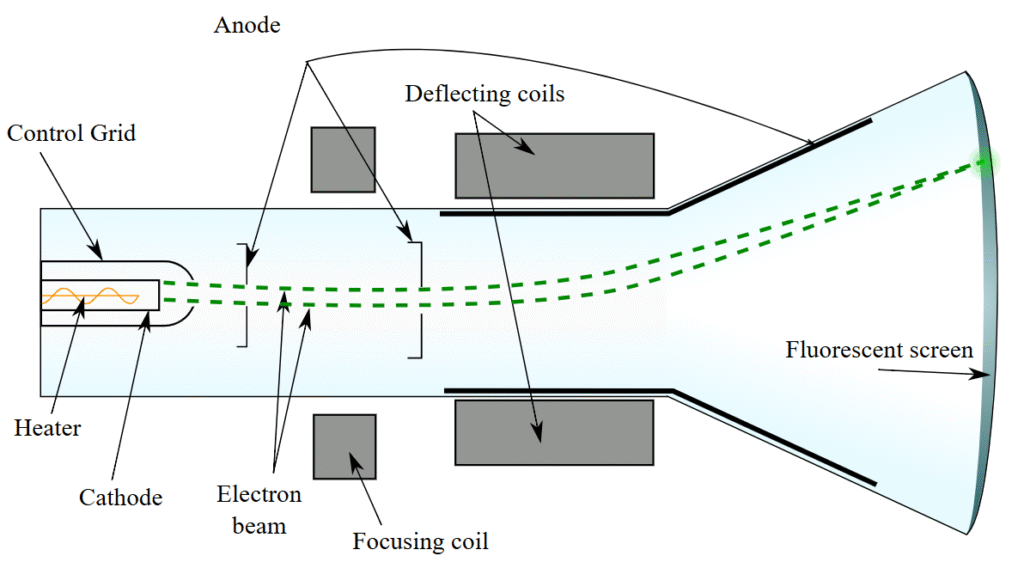
Credit: Theresa Knott (CC BY-SA 3.0)
What about colour and brightness though? Is this information somehow already contained at the level of the three guns themselves? Only partially. The ability to display colour is a property of phosphorescent screens. Phosphorescence is the emission of light for an extended period of time by a material following its absorption of light at a shorter wavelength. Essentially, it is like a partially dammed river which can receive more water than can go through it except that we are talking about high-energy photons being captured and lower-energy photons being emitted. – this has of course everything to do with electron orbitals (refer to S1 Section 2.c) and I provide the link to the Wikipedia entry for phosphorescence in the last section if you wish to understand this better. Zinc sulphide (ZnS) was a popular chemical compound and it could be activated by silver (ZnS:Ag) to emit blue light or by copper (ZnS:Cu) for red light. These phosphors would be laid on the screen in an alternating pattern and the electron guns would be mounted in a manner reflecting this pattern such as an equilateral triangle arrangement.
So, the equipment now has to target the right spots with the right energy level to convey chroma and luma properly. Overall image brightness can be achieved by increasing voltage but relative brightness between spots is controlled by changes in voltage at the time the electrons are being made to converge out of the cathode to create the electron beam. Thus we have three electron beams being fed a signal from three different channels and hitting their respective coloured phosphors on the screens.
All that is left to do is ensuring the beams only hit the relevant phosphors and this can be achieved by interposing a patterned filter or mask in between the origin of the beam and the screen. Shadow masks use a triangular pattern of holes that would be matched by the pattern of the phosphors on the screen and the second popular method uses aperture grills with vertical strips, each corresponding to one coloured vertical strip on the screen, alternating red, green and blue.
Being analogue, CRT televisions did not really have the same concept of resolution that digital TVs had; the only change in resolution was the different number of horizontal lines between PAL-SECAM and NTSC. Not so with pixels.
e) Modern display technologies
When a digital signal is recorded and needs to be displayed, it is not simply the total number of pixels which needs to be standardized and taken into account but also their distribution, that is how many lines and how many columns. The number of pixels per horizontal lines (the number of columns) by the number of pixels by vertical line (the number of rows) yields the aspect ratio. At the time of the CRT TV the standard was 4:3, which is not far off the √2 of A3, A4, A5 paper, etc. Nonetheless, for an improved cinematographic-like experience, the 16:9 aspect ratio has now come to dominate, probably because modern screens are not hampered by the same electron beam deviation-related considerations.
Applying 4:3 to the 480 visible horizontal lines of NTSC translates into 720 horizontal pixels, a format known as 480i and for the 576 visible lines of PAL-SECAM, this same 720 horizontal pixels number was preserved to create the 576i format, meaning the aspect ratio of the pixels between these formats is a little different. The next resolution step up is high-definition TV (HDTV) and from then on the aspect ratio I mention is always 16:9; it starts at 1280×720 pixels resolution for 720p and increases to 1920×1080 pixels for 1080p with 1080i corresponding to the interlaced version with half the number of pixels for each frame but the same physical number of pixels on the screen. Moving on to ultra-high definition (UHD), 4k is 3840×2160 pixels and 8K is double that with 7680×4320 pixels.
Reading and trying to absorb these numbers, 33.2 million pixels for 8K with 60 or more frames per second, the challenge of transmitting such large streams of data becomes evident and complex multiplexing and ever more intricate compression techniques are truly needed.
The first large-screen TVs that came to replace the iconic CRT television sets used plasma technology. These also relied on a phosphor coating for colour but they are activated individually in compartmentalized cells, one for each RGB colour and a 3-cell RGB block forming one pixel. As we have seen in the previous section, activation occurs when the phosphors absorb high-energy particles, in this case ultraviolet photons emitted by a gas, typically mercury vapour in tiny concentration and mixed with a noble gas which by definition does not easily react. It is called plasma because when significant voltage is applied the gas becomes ionized and some of the flowing electrons cause, through collisions, an increase in the energy level of the mercury atoms which they shed by emitting the photons. Plasma screens can offer high resolution, quite deep blacks and wide viewing angles but they are power hungry, especially when brightness is being pushed, and are subjects to a few potential issues such as screen burn-in, when the phosphors in one or several pixels have been overheated because the same image is being displayed for too long.
The technology that superseded plasma was liquid-crystal display (LCD), it already existed but, initially, large screens were comparatively much more expensive to manufacture. Liquid crystal is a state of matter endowed with the property of a liquid such as fluidity as well as those of a solid, including – and this is key – common orientation. The concept of LCD displays is as follows: #1 shine white light from tiny LEDs onto subpixel cells, #2 dress the subpixel cells with red, green or blue filters to form a pixel block each with the three primary colours, and #3 use a thin array of MOS transistors to control the blocking or letting through of the light coming from the LEDs before they reach the coloured filters. The on/off blocking of light is achieved by having two polarizing optical filters placed on either side of a layer of liquid crystals. Typically, but not always, the two filters are polarized with a 90° offset and the liquid crystal molecules are arranged in an helicoidal shape which, when not subjected to an electrical field, shifts the polarization of the backlight by 90° and thus lets the coloured filters be illuminated. On the contrary, when the transistors apply an electrical field, in line with the binary signals they receive, this untwists the molecular arrangement and the backlight polarization (a result of the first filter) is not offset so it doesn’t go through the second polarizing filter. By applying intermediary voltage levels, it is possible to control the amount of light shining through, which corresponds to the potential value of R, G and B in the RGB colour space. And by adjusting the brightness of the backlight, it is possible to control the brightness of each pixel in relation with the others.
In OLED technology, the prevalent one in consumer screens, including the active-matrix OLED known as AMOLED, there is no backlight and the light emission comes from a layer of organic semiconductors framed by two electrodes. By the way, organic doesn’t suggest life, it simply implies the presence of carbon-hydrogen or carbon-carbon molecular bonds and the molecules of the substrates behave somewhat similarly to semiconductors from an electrical standpoint. Instead of a valence band we have a highest-occupied molecular orbital (HOMO) whereas the conduction band is substituted for a lowest-unoccupied molecular orbital (LUMO) and in semiconductors where the bands are close to each other without overlapping, it is possible to induce a flow of electrons from the valence/HOMO to the conduction/LUMO band by applying some electric current as an external source of energy. This leaves an electron hole in the HOMO and an extra electron in the LUMO, which is not a stable state and the extra electron will normally recombine with the electron hole, shedding the extra energy to go to a lower orbital by emitting a photon. And there was light!
If you have followed the above closely, this means each sub-pixel can be lit independently and when none of the RGB subpixels is lit, we can have a much deeper black than in an LCD screen relying on backlighting with filters that are always going to let a tiny fraction of light through. Interestingly, different organic semiconductors can have different gaps in terms of energy levels between the HOMO and LUMO and this translates into the emission of photons with different energy levels, which we perceive as different colours. Hence, it is also possible to use three types of emissive layers for red, green and blue sub-pixels – and do away with the colour filters.
f) Trivia – Electronic paper
Millions of pixels, dozens of frames per second, brightness and contrasts, 96Hz sampling rate and 24 bits depth, all of these are important factors in delivering quality video and audio but when it comes to plain text, and specifically the act of reading text, this may prove secondary, if not unnecessary or even counterproductive in the case of sustained light emission creating screen fatigue. On this basis, electronic readers deserve a different display technology, and I mean the “deserve” because however much I enjoy the tactile feel of paper books, e-readers offer great convenience and require no cutting of trees – though electronics manufacturing does also have its own environmental footprint. Within the convenience bucket are the ability to store hundreds of books on one device because the amount of digital data in a book is in the order of a few MBs, not GBs, new titles can be purchased or borrowed from a library online, and a battery can hold charge for several weeks as compared to at best two or three days with a smartphone on plane mode.
The main drivers of the long-lasting battery are, as mentioned above, the lack of light emission and the low refresh rate, and when I say low this is no exaggeration because most e-reader software will only trigger a refresh when you turn a page, or the e-reader equivalent of this action. This of course suggests the text being displayed remains static and visible when not refreshed. There are a few types of electronic paper technologies but I will only quickly explain the most popular one called electrophoretic display (EPD).
Electrophoresis is a phenomenon occurring in a fluid whereby the application of an electric field causes a movement of particles with an electrically-charged surface; a particle with a positively-charged surface will be moving in direction of the oppositely-charged source of current. Therefore, by layering a liquid containing such electrically-charged particles between two conducting plates, the front one being transparent and serving as a display, it is possible to attract the particles towards either the viewing side or the back side. The simplified road to e-paper requires a further two conditions: the first is the segmentation of the electrodes into arrays of transistors that can switch electric current polarity, thus effectively creating the equivalent of pixels, and the second is the devising of particles that can be perceived in either black or white depending on the direction of the current.
In the early versions this would be realized by adding insoluble pigments made of titanium dioxide (with a positive surface charge) that appear white because of their high refractive index as well as a dark-coloured die appearing black because of its light absorbing properties. Thus, the viewer sees a white pixel if the pigment is on the viewing side and black if it is on the back side, with the light being absorbed by the intervening dye. The more modern version uses the micro-encapsulation of white and black pigments with opposite electric charges; the principle is the same but it allows for the use of plastic rather than glass electrodes and higher resolution.
g) Further reading (S4C8)
Suggested reads:
- Wikipedia on Colour space: https://en.wikipedia.org/wiki/Color_space
- Wikipedia on Broadcast television systems: https://en.wikipedia.org/wiki/Broadcast_television_systems
- Wikipedia on Inter frame: https://en.wikipedia.org/wiki/Inter_frame
- Wikipedia on Phosphorescence: https://en.wikipedia.org/wiki/Phosphorescence
Previous Chapter: The Camera
Next Chapter: The Smartphone & GPS