>>> Click here to access this episode of the Syllab Podcast on Spotify <<<
a) Fundamentals of telecommunication infrastructure
Telecommunication is often defined as the transmission of information over long distances, meaning longer than the human voice can carry. However, this misses the speed aspect, the fact such transmission happens within a matter of seconds or sometimes near instantly, as far as human perception is concerned. If not for this speed element, then postal services would qualify and clearly this is not what we have in mind. In telecommunication technologies, the signal is electromagnetic in nature, be it radio waves or electric pulses.
Obviously, we do not express ourselves by way of electromagnetic waves, nor do we understand them except to the extent waves in a visible spectrum of light hit our retina but even then, we could not make sense of anything other than a graphical representation. Accordingly, the information needs to be delivered to a device that will transmit it over a certain medium, be it wired or wireless, and then received by another device. Quite suitably, these devices are called transmitters and receivers, respectively.
On the back of an original signal such as sound waves in the case of voice input, the transmitter will produce a new signal conveying the same information as faithfully as possible in the form it is designed for, such as electric current in the case of a wired telephone or radio waves for a radio antenna. At the receiver end, the nature of the collected signal will also likely be changed, from electric current to sound waves or to text displayed on a computer screen.
As we have seen in Chapter 2 however, a signal originating from a human will be analog, i.e. encoded as continuous sine waves, and that from a machine can be digital or analog, while some transmission media are designed for digital signals and others for analog ones. Hence, some encoding and decoding may be required in the process. If you are unsure how an electrical signal can be considered analog you may want to refer to S1 Section 8.a on electric current but, in a nutshell, it has to be alternating current (AC) and the information lies in the frequency, amplitude and slope of the wave – the technical term for the shape is the phase. This being the case, transmitters may need to be equipped with a modulator or a demodulator, likewise for a receiver, and since in 2-way communication (called “duplex”) the transmitter and receiver can be the same device, these modulator-demodulator combination can also be built as a single device colloquially known as modem.
Modulation can be thought of as the shaping and timing of sine waves, it is the embedding of information into a signal, including the embedding of digital information into an analog signal. Demodulation is the reverse process and the main indicator of performance is the data throughput expressed in bits per second. At the outset of the internet, dial-up modems using the copper wire infrastructure of standard telephones had speeds of 56 kbit/s whereas in 2025 some countries had an average broadband speed in excess of 300 Mbit/s. We will look at the phone technology in section d) and broadband in S4 Section 5.c.
Unsurprisingly, the concept of modulation is quite similar to the encoding of data on various form and substrates, in particular the magnetic storage seen in S4 Section 2.d and the optical storage explained in S4 Section 2.e. The two central ideas are:
- Firstly, the number of states or values that need to be represented in a digital format is finite and is a function of the length of each “word” or information unit. For example, using binary data and a byte of 4-bits as the unit of information, there are 24 = 16 possible representations or symbols that one need to encode.
- Secondly, a “1” and a “0” can be represented as change or no change in a particular dimension or property, as opposed to one of two absolute values.
On that basis, the most frequent modulation techniques consist in varying only one of the properties in a string of sine waves: their phase, their frequency or their amplitude. The technical names for this are phase-shift keying (PSK), frequency-shift keying (FSK) and amplitude-shift keying (ASK), respectively. Some techniques also adopt a blend of the above, such as phases and amplitudes. Let us look at PSK to understand this better and then the overarching principles will apply to most other techniques. Quoting from Wikipedia, “a sine wave of arbitrary phase can be written as the linear combination of two sine waves with phases of zero and a quarter cycle, the sine and cosine components, respectively”. Hence, it is possible to modulate the phases by altering either only the sine, the cosine or both the sine and cosine inputs, the latter being called 4PSK or Quadrature PSK. Indeed, by selecting two sine values on a 360° circle (so they face each other 180° apart) and two cosine values shifted by 90° from the sine values, we can represent 2 bits of data or 4 symbols in each wave and the symbol will change whenever either the cosine or the sine value changes, which translates into a phase shift. On a diagram, the point located at 45° (or 1/4 π) on the circle corresponds to (11), 135° (or 3/4 π) is read as (01), 225°/-135° (or 5/4 π) as (00) and 315°/-45° (or 7/4 π) is equated to (10).
If you want to visualize what this means in terms of wave shape and behaviour, Figure 3A shows a sine and a cosine functions; note the axial symmetry of cos(x) for values 0 and π and the origin or odd-symmetry of sin(x) for those same values. If we consider the circle, the output of the sine function will be positive above the horizontal axis and negative below and for the cosine function it will be positive on the right side (from -1/2 π or 3/2 π and up to 1/2 π) and negative on the left. When both waves are merged as in Figure 3B, we can see reversals around the origin, or around a vertical axis, or both.
I have inserted the link to the Wikipedia entry for PSK at the end of this chapter if you wish to read more on this encoding technique and the entry for Phase modulation might also prove useful as a complement.
Figure 3A: Sine and Cosine Period
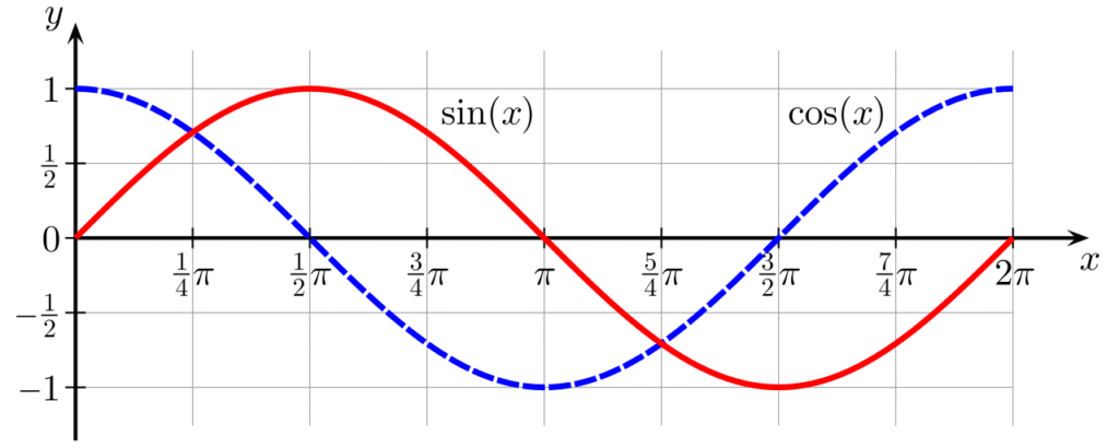
Credit: Geek3 (Public Domain)
Figure 3B: QPSK diagram
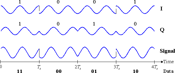
Credit: Splash (CC BY-SA 3.0)
The job of the demodulator is to convert the analog signal either back to the original format or to another one. The first imperative for the equipment is knowing the nature of the modulation and the list of symbols or patterns being used so it can detect and then decode them. It seems straightforward but the signal may have travelled long distance and be attenuated and deformed so, before the detection and mapping, the demodulator will generally amplify the signal and also try to rectify it or “clean it up”.
So, do we have everything for wired or wireless communication here? Not quite, unless you are happy being limited to walkie-talkies. What is missing from the picture is the network infrastructure which allows for the sharing of long-distance signal carriers. This includes the medium carrying the signal in the case of wired communication as well as the equipment that will direct traffic from one sender to one or several recipients and ensure the strength of the signal is maintained above a certain threshold to guranty proper decoding at the receiver end.
Repeaters are used for various media of propagation, including to amplify a light beam in optical fibre, an electrical signal in a telephone line or undersea metal cable, or to receive and re-emit a radio signal. These repeaters have to be powered and in the example of the telephone line, the electric current loses power as heat due to the resistance of the copper wire, so the repeater uses DC power to boost the signal amplitude.
As for the matter of getting the signal from the emitter to the intended recipient, and this is applicable for point-to-point communication as opposed to broadcasting to anybody who may want to listen, this is the domain of routers and switches. The former will forward data across networks on the basis of the network address contained within the data, and the latter will take care of the “last mile delivery” within the local area network (LAN). This will be described a little more in section d) on telephony.
b) Multiplexing and addresses
Great, we have everything we need this time around, transmitter and receiver with embarked modem, switchers and routers, a wired metallic or optical fibre cable, and users. Plenty of them since this is a shared resources. Clearly this means the wire needs to be able to carry many signals simultaneously, possibly in opposite directions, and we need to be able to locate the intended recipient.
The locating of the recipient is very much like the fetching of data in computer memory, the solution is to provide an address for each user. For mail delivery the address would consist in a country, postal code or city, street name and house or flat number. For telephony, it is a phone number, possibly with a country code in front of it for international calls. If your call remains within a local network then you may have a shorter version as it doesn’t need to be routed across countries and regions. Same for businesses with internal calls where the last 4 digits may be used perhaps. The internet IP address serves the same function and naturally it works a little differently with mobile devices since the geographic location is not fixed, hence the network they are connected to and their position within this network are both variable. The solution is simple enough conceptually though a little more challenging to realize with very little latency in practice: your mobile phone, when it is connected to the network, informs the local telecom towers of its presence so the address book of each local network gets updated and the information is consolidated at a wider geographic level. Knowing roughly where you are located, when your number is dialled up, the closest towers all send a signal to your phone and it is your device which decides which one offers the best connection and uses this one.
Now, multiplexing. Imagine you have three persons with three flashlights of colour red, green and blue who want to communicate a signal consisting of on/off light pattern to three recipients, or to you only, it doesn’t matter. There are three main ways they could do so: #1 position themselves next to each other and transmit the message concurrently so the signals travel side by side, #2 each transmits for two seconds, then let the next person transmit for two seconds, same for the third one and then the first person resumes for another two seconds, etc., and #3 combine the beams of light into one and each person transmits their own signal concurrently so you get to see a pattern of shifting colours, including white when all three beams are emitting at the same time.
#1 is called spatial division and can be done if the medium has several physical channels, as a telephone line would and so would a fibre-optic cable. #2 is called time division and this sequential way of transmitting information works well when the speed at which the information is transmitted by batches is significantly superior to the speed at which the information is processed by the end user. If 10 persons record an audio message of 10 minutes each one after the other on 1 tape or mobile phone and then this content is transferred over a wire at 10 times its original speed then this would only take 10 minutes. Provided the recipients listen to the messages at a normal speed, you have essentially shared one common resource across 10 users without anyone noticing. Finally, #3 is called frequency-division and as our example suggests, it works best for wave-based signal, i.e. of an electromagnetic nature. For light, it can be reverse engineered by the demultiplexer and for radio wave, one would just tune into the right frequency channel. Note that for electromagnetic waves, it is also possible to combine signals with different, orthogonal polarization. This fourth option is called polarization-division.
If you have read S4 Section 2.a on computer architecture, you may recall about the databus in your computer. It is a good example of shared resources with limited bandwidth and sure enough it heavily uses multiplexing by slicing data into smaller packets (say 16 bits transferred as 2 times 8 bits) and transfer information sequentially.
c) Electrical telegraphy
The first version of the telegraph, which translates into “writing over distance”, was optical in nature and relied on a preset array of light patterns. Using electricity rather than light as a medium, the telegraph eventually became the first real telecommunication system in the world. The ingredients were relatively simple, or so it seems nowadays: a transmitter, a metallic current-conducting line, a receiver, and an agreed-upon method for encoding and decoding signal with Morse being the most successful system. This code is binary in nature, made of short and long dashes (technically called on-off keying and a dash represents the presence of light or current) named dits and dahs, respectively. Instead of having a typical symbol length of say 6 bits which could encode 26 = 64 symbols, the numbers and letters of the alphabet were represented by as few as one dash and as many as five with the following rules: one dah last as long as 3 dits, symbols are separated by a space or off-key with a duration of 1 dit and words are separated by spaces lasting the equivalent of 7 dits. For a human listener it may have been challenging but once written down or automatically decoded by an electronic device, the room for error was minimum.
To facilitate the automation of the process, in particular for purpose of teleprinters, the Morse code gave way to the fixed-length Baudot code (later improved as the Baudot-Murray code) consisting of 5 bits which on paper can only represent 32 symbols but 2 symbols represented “shift to letters” and “shift to figures” so all the alphabet, numbers and even some punctuation and control symbols could be accommodated. Furthermore, special devices with 5 keys were produced, analogous to a piano, so an operator could key each symbol in cadence with a clock. As the technology for circuit-switching developed, thus making the need for human operators redundant, the teleprinter would eventually evolve into telex machines where “telex” stands for telegraph exchange.
In the second sentence of this section, I stated that the telegraph was the first real telecommunication system in the world and this is no exaggeration because the networks spanned and eventually linked most of the world, physically bridging continents thanks to lines suspended above poles as well as via oceanic cables. The first undersea cable was actually laid as early as 1850, across the channel between France and England, and a cable across the Atlantic was eventually successfully laid down and operated at the third attempt in 1866. The cable was made of 7 strands of very pure copper with a total weight of nearly 100kg/km including the insulator and measured about 4300 kms. Unfortunately, because repeaters or relays need to be powered, these telegraph cables never benefitted from them and the 1866 cable could only achieve a throughput of 120 words per minute. The first transatlantic cable with repeaters would have to wait for another 90 years and by then it would be engineered for the telephone.
d) The telephone
The telephone as many of us knew it is pretty much a relic of the pre-mobile era though the devices we can still find in offices and to a lesser extent smartphones still share many design elements. Similarly, the telephone line infrastructure with its copper wires is very much part of a legacy and are being replaced by optical fibre in many countries. Yet, the telephone and the network developed for its usage really is the textbook study in wired telecommunications and thus deserve a dedicated section in this chapter.
Let us begin with the device itself; there is a keypad or rotary dial to input the address (that’s the phone number) of the recipient, a microphone (transmitter), an earphone (receiver), and a jack for connection to the wire. The jack wasn’t always a thing and initially the wire was connected to the device but as it became ubiquitous it proved easier to standardize a connection, lay cables to one or several points in the house and residents could then buy a phone and plug it themselves.
Microphone technology was and still is key in preserving the signal quality and therefore the integrity of information. Its purpose is to convert the pressure waves of our voice into electrical signals, be they analog in the past or digital nowadays. The first commercially successful version was called a carbon microphone and worked by using the pressure of the sound waves to push together carbon granules that would conduct more current as pressure increased, so it was a rather crude transduction. The technology that became prevalent and is still used in many phones and professional recording equipment is called condenser or capacitor microphones. It relies on a set of 2 plates in an electrical circuit, the diaphragm in front and the back plate, which are spaced but act as a condenser, meaning they can store some electricity – this property is known as capacitance. The sound waves apply pressure to the diaphragm and these movements create shift in the capacitance, which in turn generate analog electrical signals. A variation of the condenser uses a dielectric material, essentially the electrostatic equivalent of a magnet, thus providing a constant charge to the capacitor and the movement of the diaphragm changes the capacitance, which mathematically and physically results in a change in voltage embedding the signal; these are called electret microphones.
For a speaker, to keep it simple, picture the reverse: the electrical signal drives motors to produce linear movements, back and forth. Those motors are connected to one or several diaphragms and their movements create pressure waves that we perceive as sound.
Shifting to the telephone lines and network; quite quickly the model evolved to a pair of copper wires to create a circuit and those pairs would be twisted to address the issue of external electromagnetic interference and reduce the amount of disturbance created by the proximity of two electrical circuits. The reason why twisting works is because on average the two wires would be affected equally and this can be filtered out; so this twisting happens on the pairs of wires leaving individual residences as well as on the telephone lines suspended above ground on poles in non-urban areas, with the lines switching sides at the top of the poles.
The copper wires would physically link the telephones with a local exchange and thus form part of the local area network or local loop. Before automation and phone numbers, a manual operator would then connect the call initiator with a trunk line connecting the local loop with a wider network, and eventually the connection would be made with the local loop of the recipient who accepts the call, thus establishing telecommunication. The consolidated web of all telephone networks globally is called the public switched telephone network (PSTN) and over time it has been augmented and upgraded to include, inter alia, cellular networks, satellites and fibre-optic cables.
e) Optical fibre
The world did not move straight from the first telephone lines to fibre-optic and for several decades the repeater issue faced by undersea telegraph cables was addressed thanks to coaxial cables. Since one of the issues was the powering of repeaters, the obvious solution is that the cables themselves had to carry electric current – high powered direct current. To minimize the loss of signals, the signal-conducting wires at the centre are encased into an insulator which is itself surrounded by a woven metallic structure acting as a shield preventing energy leakage by physically restricting the electrical and magnetic fields. It is this ability to carry signals with hardly any loss in quality that still makes coaxial cables relevant today.
However, even despite their ability to support frequency-division multiplexing, the bandwidth of coaxial cable became too much of a bottleneck in comparison to that offered by fibre-optic, although the shift from analog to digital allowed for time-division multiplexing.
The advantages of light as a medium to carry information versus electricity include no electromagnetic interference, the ability to do wavelength-division multiplexing, and, provided high-grade glass and other materials are used, lower signal attenuation over long distances, thus requiring less optical repeaters. Note that a fibre-optic cable also does carry high-voltage direct current to power those repeaters or amplifiers. The two aren’t exactly the same, I will not go into the details and instead I include a link to the Wikipedia entry for optical amplifier if you wish to know more, but the idea is that the amplifier will transfer energy to the laser beam without altering the wavelength and the repeater will transduce the optical signal into an electrical signal, amplify this electrical signal and then transduce it back to an optical signal.
The working principle of optical fibres is to guide the light waves to their destination; this is made possible because, when their diameter is only a few times more than the wavelength of the electromagnetic waves they carry, they act as guide. They are assisted in their job by a thin cladding with a lower index of refraction than the main core medium, thus confining the waves to the core. Here again, I will not stray into the optics but include the link to the Wikipedia entry for waveguide in this context in section g). These strands are then enclosed in protective layers and bundled together, up to several hundred in a very large cable.
The quantum of loss in light intensity is a function of the fibre quality and the wavelength, the longer it is the lower the loss. For example, for a wavelength of 1310 nm it can be as low as 0.35dB/km, which is a loss of about 8%. Hence, the lasers beamed are in the infrared part of the electromagnetic spectrum and undersea cables with top-end glass can go more than 100km without repeaters or amplifiers, all this with round trip delays across the Atlantic of less than one tenth of a second.
In many countries, optical fibre has also become ubiquitous in residential areas, offering customers transfer speeds that are theoretically symmetrical for download and upload, and only limited by the service provider or other equipment rather than the cables.
f) Trivia – Dial-up Internet access
We’ll explore the nature and operations of the Web and the Internet properly in Chapter 6 but, since we have mentioned the good old telephone and the copper wires that carried its signals, I thought it would be interesting to understand how this existing network was leveraged by a brand-new technology.
As explained in section b), routing data requires both a network and an address. In the case of internet, the addresses were not an add-on feature but a fundamental feature of the concept, so the making use of the copper wires and the entire PSTN only required the development of a bridging device in the form of the dial-up modem.
Such modem transduced digital signals into the same type of analog electrical signal used by traditional telephone, this would be routed to the internet service provider where the analog signal would be demodulated into a digital data stream and an internet connection would be established. Same thing for data travelling the other way though no more dialling required once the connection is live. Et voila! Up to 56kbit/s without laying new lines… And for the younger readers with a smirk on their faces, just know it was amazing for the time. Of course, house phones were not originally designed for such use case and there were no spare wires so one data user would block the line for potential voice calls. Still, at least the option was there thanks to some astute engineering.
g) Further reading (S4C4)
Suggested reads:
- Wikipedia on Phase-shift keying: https://en.wikipedia.org/wiki/Phase-shift_keying
- Wikipedia on Optical amplifier: https://en.wikipedia.org/wiki/Optical_amplifier
- Wikipedia on Waveguide in optics: https://en.wikipedia.org/wiki/Waveguide_(optics)
Previous Chapter: Programming and operating computers
Next Chapter: Radio & Wireless Networks