>>> Click here to access this episode of the Syllab Podcast on Spotify <<<
a) The meaning of the grid
In each of the three previous chapters, we have explored several methods of producing electricity. Having covered the generation aspect, we can now naturally turn our sight towards the distribution. But of course, it is not as straightforward as that because, with some exceptions for heavy industries, the location of electricity generation assets does not coincide with that of consumers, nor would we want this to be the case. Accordingly, in addition to distributing electricity, there needs to be electrical lines ensuring the medium to long-distance transmission. This infrastructure is called the electricity grid, which I will abbreviate as “the grid”, and because it can span various generation assets and many consuming areas, it can play a further role: the optimization of the supply and demand sides. Not only does it ensure that the load is balanced but it can also sometimes request for some assets such as hydro dams to kick in and bring in more supply but it can also shed load.
There are four primary ways demand can be decreased:
- Entering into an agreement with some industries to lower their electrical consumption at specified peak hours;
- Provide incentive to residential and commercial consumers to shift their consumption towards periods of lower demand through differential pricing (peak period being much more expensive than low period);
- Lowering the voltage to certain areas of the grid, this is called a brownout; and
- Stopping the supply to parts of the grid, this is called a blackout and may or may not be voluntary because it is sometimes the result of a failure somewhere within the grid, which may be triggered by one of the generating assets and can lead to a cascade of failures within the interconnected system.
In the next section, we will spend some time understanding the nature and characteristic of the electric current within transmission lines as well as the materials they are made of. And in section c), we will look at the equipment and technologies involved both for feeding generated current into the transmission lines and, further away, to ensure the current from these lines finds its way to consumer outlets in a format that does not damage all their equipment. Before that however, it is worth noting some architectural similarities between the grid and the internet, as described in S4 Section 6.a. The internet is a network of networks, and so is the grid. There is not just one grid, there are several of them and in turn they are connected by meta-grids.
At the local end are the microgrids linked to the main grid, the macrogrid, but that can also be disconnected from it by relying on local generators. This is a necessary element in the development of distributed generation where smaller generation assets can serve isolated communities. Typically those assets would use renewable energies such as solar and small hydro, or even geothermal power.
The technical term for macrogrids at the regional scale and above, and here region may mean several countries or states, is wide area synchronous grid (WASG). Provided macrogrids are synchronized, meaning with identical alternating current (AC) frequency and standards, they can indeed be connected and treated as a broader unified net. If the AC frequency is not in phase then variable frequency transformers can be used and if direct current (DC) is used then there is no phase synchronization issue to worry about. To give you a sense of scale, the Continental Europe Synchronous Area (CESA) spans at least 35 countries, is phase-locked at 50Hz with automated processes to ensure no problematic deviations, and it supplies electricity to more than 500 million customers.
There can be further linkages between macrogrids but those are generally meant for trading purpose rather than for balancing load in a given region. These connections would see generating assets in a region exporting their electricity to another macrogrid via high-voltage direct current.
b) The physics of electricity transmission
In the context of alternating current, using only one phase means there is no constant flow of electricity being produced, it goes up and down in line with the sine waves of the one phase. Using two phases separated by 180 degrees, so that one phase peaks on the positive side when the other peaks on the negative one, we can have a constant flow but it isn’t optimal because the fluctuations are stronger, which is not good for some equipment, and it isn’t as efficient compared to three phases in terms of neutral-current cancellation. As for four phases and above, the incremental benefits compared to three phases do not justify the complications at the infrastructure level and so three phases it is.
These phases are separated by 120 degrees, thus when one peaks the other two are both at half the peak amplitude with an opposite charge. At any time, the sum of the three phases is equal to zero and therefore the return neutral wire can sometimes be dispensed with. Meaning it takes 3 wires to carry three times the amount of current that would be carried by a one-phase system requiring 2 wires, the conductor and the neutral one to close the circuit. This is quite some savings.
Over very long distances, running AC current through AC/DC converter stations and then transmitting DC at high-voltage before converting it back can be worthwhile in terms of minimizing transmission losses due to wire resistance. The reason why high-voltage is preferrable is because electrical resistance increases with the square of the current level and since power is voltage multiplied by current, the same amount of power can be transmitted by stepping up the voltage and the current will decrease in an inverse proportion. For example, if I double the voltage, then the current will halve and the losses due to resistance would be divided by four (being the square of two).
In order to further decrease electrical resistance, the shape of the wires, thicker is better, and the nature of the material are also important. What we are looking for is the opposite of insulators with tightly-bound electrons; we want conductors and the best candidate for those are metals because the electrons are more loosely bound and can act as charge carriers, providing current to the load, the technical term for the device consuming electricity, by colliding with each other and thus transferring momentum along the metallic wires. Copper is one of the two main favoured conductors because of its low resistance and relative affordability compared to a few other candidates such as silver. The other is aluminium, it is not as conductive as copper but it is a lot lighter and cheaper to deploy. I enclose a link to the Wikipedia entry on electrical resistance and conductance at the end of this chapter if you wish to read more on this topic.
We will look at the possibility of using semiconductors in the future, and the stumbling blocks for this to become a reality. Not now though; time to look at why we use AC rather than DC in most parts of the grid, how to convert AC into DC or the other way around, and how to step voltage up from generators into the grid and then down from transmission lines into distribution lines and, eventually, to the loads.
c) Playing with electricity
Bearing in mind the advantages of high-voltage DC transmission, why is most of the grid on AC then? If you scour the internet you may come across the “war of the current” and conclude this is a historic technical legacy. This would be misleading because part of the reasons that saw the adoption of AC are still very much valid today, even though technological advances have partially negated some of the advantages.
In a nutshell, there are four main arguments in favour of AC: #1 transformers only work with AC, #2 most of the generating capacity outputs AC, #3 it is easier to isolate the load from the power supply, which is a safety concern, and #4 there is no risk of a spark being produced when switching off equipment drawing AC, as opposed to DC.
Of these arguments, the key one is certainly the first. As mentioned earlier, to avoid too high a level of transmission loss, the voltage of the power supplied to the grid should be increased to very high levels of 110kV and above in most cases before being stepped down to levels generally in the range of 2kV to 35kV for the distribution part of the grid and then, again, to the 200-240v or 100-120v ranges that are standard in residential outlets across the globe. More on this in section d).
The way this is achieved can be described as a three-step process. On one side of the transformer, that of the supply called “primary”, the electric wire is coiled around a magnetic core. On the other side, another electric wire is coiled around the same magnetic core, and this wire will carry the “secondary” power away. The third part of the process is straightforward: the varying current of the primary current induces a magnetic flux which, in turn, induces a secondary varying current with a similar phase. This is useful once we know that the voltage is a direct function of the number of turns of the coil around the magnetic core. So if the number of turns in the secondary winding is higher than in the primary, then the current is being stepped up proportionally, and conversely, if it is lower then the current is being stepped down. A visual illustration is provided in Figure 1 below.
And this obviously doesn’t work with direct current because it produces no change in the flow of current and therefore no change in the magnetic field and no secondary current is being induced. This explains why the transformers found in power substations rely on AC.
Figure 1: Ideal transformer and induction law
Credit: by BillC (CC BY-SA 3.0)
To get from DC to AC, the main equipment used is called a power inverter. The central concept is to synthetically build a sine-wave-like current output by first using switches to change the direction in which the current flows in a circuit and, secondly, to shape the resulting square waves so they end up looking like sine waves by varying the timing and duration of the inversion and using filters. The two filters in this case are inductors and capacitors. The former act like a magnetic flywheel with inertia, and the latter can hold an electric charge. Using both in combination, the edges of the square waves can be smoothed to become curved. I include a link to the Wikipedia article for power inverter in the last section if you want to know more about the technical aspects and applications.
The technique for turning AC into DC is different; it makes use of a rectifier. Those are built around components such as vacuum tubes or diodes (refer to S4 Section 7.c) to only let current through in one direction. Three diodes can be used to let through the top part of the sine waves of alternating three-phase current and, with a switching mechanism, the bottom part of the waves can be turned upside down and let through as well. The result is pulsating unidirectional current and by adding some electronic filters such as resistors and capacitors, the waves can be partially flattened to be more DC-like.
This means that, technically, it is possible to convert the voltage of direct current by first running it through a power inverter, then an AC transformer and then a power rectifier. Nowadays, the progresses in semi-conductors and integrated circuits make it possible and efficient to use other techniques to step voltage up or down by playing with switches and filters like inductors or capacitors. For example, a boost converter will see the creation of a magnetic field and a primary long-circuit configuration and, when the switch is closed, this creates a short circuit bypassing the load (and potentially a capacitor before that) and the magnetic field disappears, thus creating additional voltage in the direction of the load. If you wish to read more about the various DC-to-DC technologies, I enclose a link to the Wikipedia entry for DC-to-DC converter at the end of this chapter.
d) Mapping secondary distribution
We now understand how it is possible to have a motley group of power generation assets scattered across a wide region, each with their phase, current and voltage characteristics, and yet have a synchronous phase-locked AC macrogrid transmitting high-voltage across long distances, which may be AC or DC, and managing to deliver alternating current to millions of loads at standardized voltage and frequencies. From there, adapters can step down and rectify-and-filter alternating current into lower voltage direct-like current to recharge batteries or power computers.
For secondary distribution, that which our home are connected to, the main voltage standards fall within two bands: 100-120v and 220-240v. As for phase frequency, it is either 50Hz or 60Hz, apparently partly for historical reasons having to do with the type of load and partly because they have many divisors, which comes in handy for deriving clocking frequencies.
North America, Central America and the northern part of South America down to Ecuador use 100-120v and 60Hz, Japan is on 110v & 50Hz, Peru and the Philippines on 220v-60Hz, Brazil and Saudi Arabia have some hybrid regimes and most of the rest of the World including Africa, Europe, Russia, China, South Asia and Australasia is on 220-240v & 50Hz. Most of these are single-phase rather than triple-phase in residential areas where the main purpose is for heating and lighting rather than powering large electric motors. Figure 2 below is a colour-coded world map of the voltage and frequency standards.
Figure 2: World map of mains voltage and frequencies
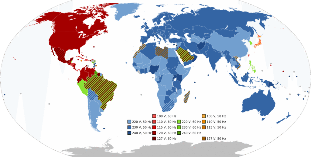
Credit: by SomnusDe, in the Public Domain
In many plug points, you may see two holes for the hot wire and the neutral one as well as a pin for grounding. The term of “ground” can have different meanings depending on the circumstances.
In an electric circuit, safety is paramount; a ground wire is an alternative, low-resistance path redirecting the current flow away from and through you, potentially, in case of a fault such as a short circuit. Generally, all ground wires in a house are physically ground into the Earth, which by definition has zero voltage, via a copper ground rod buried into the ground, thereby creating a return path which closes the electric circuit, albeit one with a very high resistance. This also serves to prevent excessive voltage build up, due to static electricity for instance.
e) Smart grids
What we call the smart grid is not a revolution, it takes the roles and capabilities of traditional grids and seeks to carry them out more efficiently and improve on them, respectively. A lot of this relies on better connectivity, not in the physical sense of conveying electric current but that of making information available on the local and overall states of the grids so as to optimize both the supply and demand sides. The improved ability to transfer data and take algorithmically-driven actions based on those is facilitated by improved and more widespread metering equipment, including on the consumer side. To be sure, the smart meters installed on the consumer side would make the information available both to the consumer and the electricity supplier.
Importantly, improved and connected sensors and metering devices can help with early fault detection and, consequently, with the prevention of potential cascading failures leading to power outages, hence improving the reliability of the system. The availability of statistical data also allows for the extraction of patterns and an improved predictability of power requirements. As mentioned earlier in this chapter, it is possible to partially increase power supply by releasing stored energy but it is a lot easier and more effective to curtail demand through dynamic pricing or technologies such as smart charging and smart consumption in general.
The idea here is that connected appliances, including electrical vehicles, can be externally controlled, rather than manually by the consumer, to shift the timing of drawing of electricity to off-peak periods as much as possible. In fact, electric batteries could even release electricity to the grid during peak periods and be paid for it. This is the idea of pooling resources and tapping existing potential before building new, costly power generation assets.
This obviously calls for bidirectionality, the ability from the distribution side of the grid to handle both outward and inward electricity flows. Such a property is not desirable only for smart-charging-like situations, it is also indispensable to the realization of decentralized generation and it is one thing to have an infrastructure handling small generating assets scattered in local areas and another to deal with such assets in each house. Indeed, this is the nature of solar panels on roofs: they are electricity generating assets and part of the attraction of this equipment is the ability to sell surplus electricity to the grid.
To improve the economics of such assets, and generally to further optimize the grid, a key piece of the puzzle is the ability to store electricity efficiently, meaning economically and without incurring too much energy losses in the conversion process. Therefore, this aspect is intrinsically linked to battery technologies and other modes of energy storage, which will be the topic of Chapter 5.
f) Trivia – Superconductivity
Our understanding of physics is still not perfect, and nobody is claiming this, so the phenomena of superconductivity (and I am using the plural intentionally here) are still not fully elucidated but, while they were certainly unexpected, they do not contravene fundamental equations such as Ohm’s law which says that electrical resistance is voltage divided by the current. If voltage is zero then there is no resistance and this is indeed what has been observed in superconducting materials: current flowing seemingly forever without applied voltage.
For this to occur, certain conditions besides the nature of the material, have to be met. These include the reaching of a critical temperature and a magnetic field not exceeding a certain flux density. The first identified semiconductors had a temperature of only a few kelvins (lead superconducts at 7K for instance) and later some “high-temperature” variants, which is defined as being above 77.3K (-195.8°C), the boiling point of liquid nitrogen, for purely practical reasons. Some higher temperature semiconductors have been devised but they tend to be brittle and hard or expensive to manufacture and the quest is on for “room temperature” materials that would not need cryogenic temperatures.
Whilst possible, wrapping electric wires with liquid nitrogen is an expensive proposition and it is unclear if the benefits in terms of reduced transmission losses would ever justify rebuilding parts of the grids. And then there is the issue of current density, defined as the intensity of the current per unit of surface area and expressed in A.m-2 (ampere per square meter). Superconductors have many applications besides the electricity grid and it doesn’t seem wise to pin our hopes for energy efficiency on this technology. Smart grids and better generation technologies can deliver much more for that purpose.
g) Further reading (S6C4)
Suggested reads:
- Wikipedia on Electrical resistance and conductance: https://en.wikipedia.org/wiki/Electrical_resistance_and_conductance
- Wikipedia on Power inverter: https://en.wikipedia.org/wiki/Power_inverter
- Wikipedia on DC-to-DC convertor: https://en.wikipedia.org/wiki/DC-to-DC_converter
Previous Chapter: Nuclear power & Hydrogen
Next Chapter: Batteries & Energy Storage